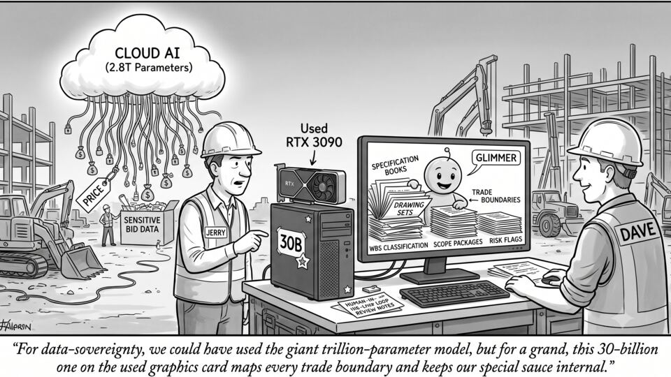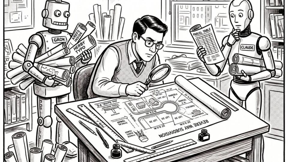
TL;DR: I gave a week-long Civil 3D homework assignment to three AI agents on the same workstation, with the same automation tools. Claude Opus 5.5, running in Claude Code, finished every required item and the extra credit in about 65 minutes while I was away from the desk, and produced a seven-sheet plan set a licensed engineer could stamp after a normal review. The same local model, Qwen3.8-Next, run once in OpenCode and once in Claude Code, didn’t get there: one stopped at the corridor and the other finished about 7% of the first item. With the harness held constant, the model made the difference. Routine production drafting is about to get much cheaper, and that changes what we should expect from entry-level engineers and how we teach them.
In the previous post in this series, Two AIs, One Subdivision, Ninety Minutes, Grok and Claude each laid out a 20-lot subdivision from a one-line prompt. One solved it; the other only looked finished. This time the assignment was bigger and the instructions were stricter.
One prompt, one homework, three agents
Homework #6 in the university BIM course I’m taking this fall is a solid Civil 3D exercise. Starting from contour lines, students build an existing-ground surface, a five-curve roadway alignment and profile, a typical section, a corridor with cross-sections every 50 feet, and an earthwork takeoff. Then, in Part 2, they lay out an unpaved road and grade a pad at 3:1 cut and 4:1 fill, balancing cut against fill with Civil 3D’s Grading Volume Tools. Everything is printed and graded against a check sheet.
I gave this assignment to three AI coding agents on the same Windows workstation running Autodesk Civil 3D 2027. The same open-source automation repositories were pre-installed for all three: a Civil 3D MCP server, a COM/AutoLISP harness, and a Civil 3D–Revit bridge.
| Attempt | Harness | Model | Where it ran |
|---|---|---|---|
| 1 | OpenCode | Qwen3.8-Next | Local, one NVIDIA RTX 6000 Pro |
| 2 | Claude Code | Qwen3.8-Next | Local, one NVIDIA RTX 6000 Pro |
| 3 | Claude Code | Claude Opus 5.5 | Anthropic's cloud |
The instruction to Claude Opus was a single paragraph. It said, roughly: read the files in this folder, complete all of the homework, and use any means of driving Civil 3D you like. Make the drawings neat, orderly and readable, with north arrows and scales and no overlapping labels. Write any tools you need. I’ll be away, so don’t ask me for help. Go.
Then I left.
When I came back, a zipped submission was waiting: a seven-sheet plan set, the drawing, the earthwork volume report, a written report with the AI commentary and extra credit, and the check sheet. From first prompt to finished zip took about 65 minutes of wall-clock time. I didn’t answer a single question, because none was asked.
Neither Qwen attempt got there. Here is how each run went.
Attempt 1: OpenCode + Qwen3.8-Next, “blocked by the API”
The OpenCode run deserves credit. It built the existing-ground surface from 27,504 contour points. It created the roadway alignment with all five curve radii correct, and the paved and unpaved layout profiles with the right end elevations. It even caught that one curve deflected right, not left, as the student’s paraphrase had said. It also extended the MCP server with a new sheet-plotting action and a grading-volume probe.
Then it hit the corridor and stopped. Its status notes give the reason:
Stock subassembly import.
SubassemblyCollection.ImportStockSubassembly(name, className, pt)throwsArgumentException: Can't find the subassembly with the classNamefor every stock name… the lanes/curb/sidewalk cannot be added headlessly. Without an assembly there is no corridor → no sample lines/cross-sections/Top-Datum surfaces/quantities.
It reached the same conclusion about grading, writing “Grading exposes 0 public methods in 2027… grading object + volume-tools nudging cannot be automated”, and closed with: “This is an upstream gap, not my fault… If the user can add the lanes/curbs/sidewalk manually in Civil 3D, the corridor/sample lines/surface/quantities will then work.”
So items 5 through 8 on the check sheet were not done: the assembly, the corridor and its Top and Datum surfaces, the cross-section printouts, and the quantity takeoff.
Grading was only partly done. Without a real grading object, the agent estimated cut and fill with an outside geometric model and got numbers far from the true values. Its extra-credit answer said the pad needed to come down about 0.3–0.5 ft. Civil 3D’s own volume tools later showed the pad had to go up 8.8 ft.
The drawings show the struggle. This is the “24×36 plan” sheet it produced:
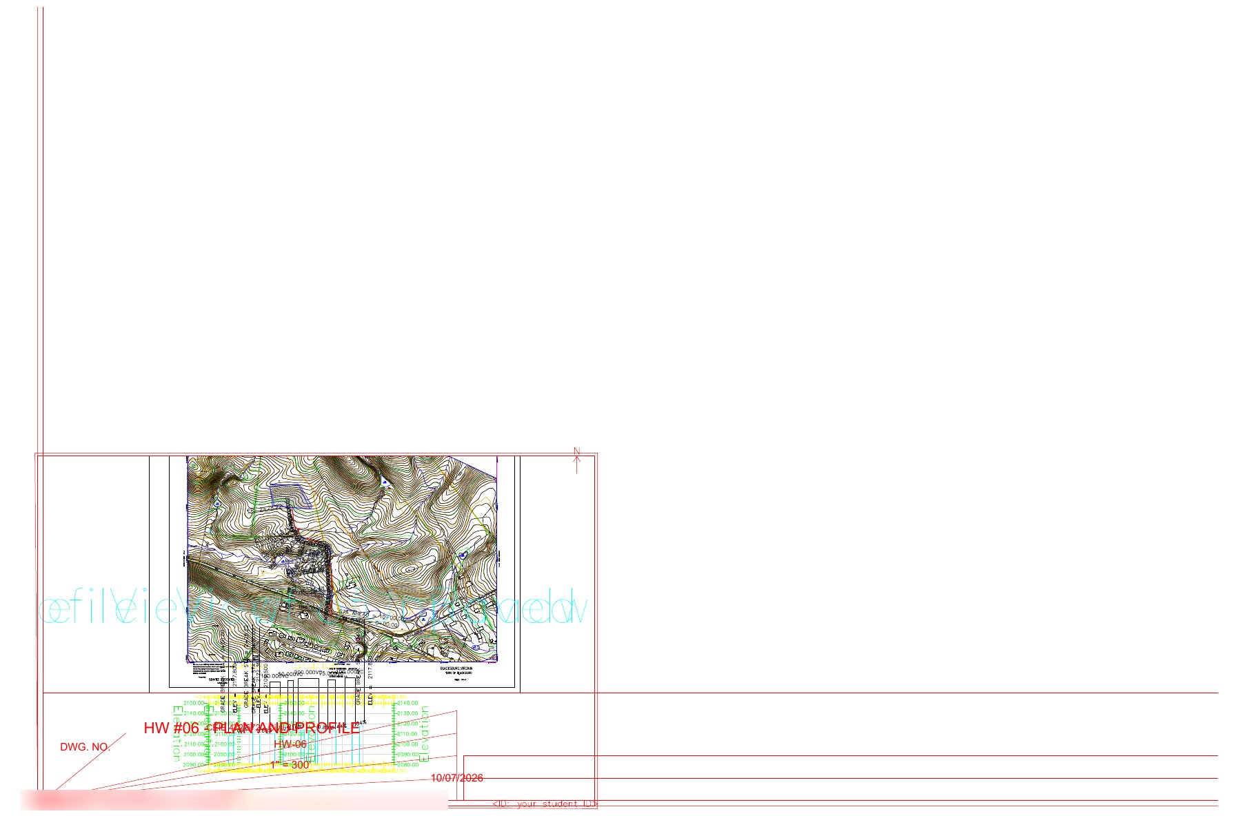 OpenCode + Qwen3.8-Next, “HW06_24x36_Plan.pdf.” The plotted content fills about a fifth of the page. Title-block text is stacked on itself, the profile view overlaps the plan, and the north arrow is a tiny tick mark.
And its “paved profile view” printout, which the check sheet requires:
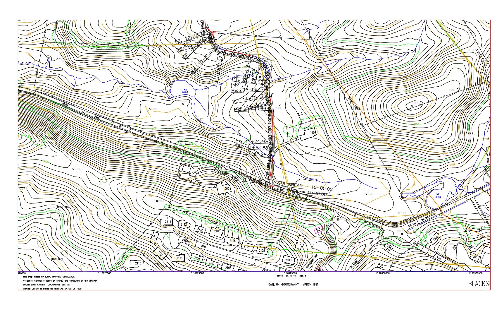 The required profile-view printout. It is actually a plan-view window of the site with alignment labels. No profile grid is visible.
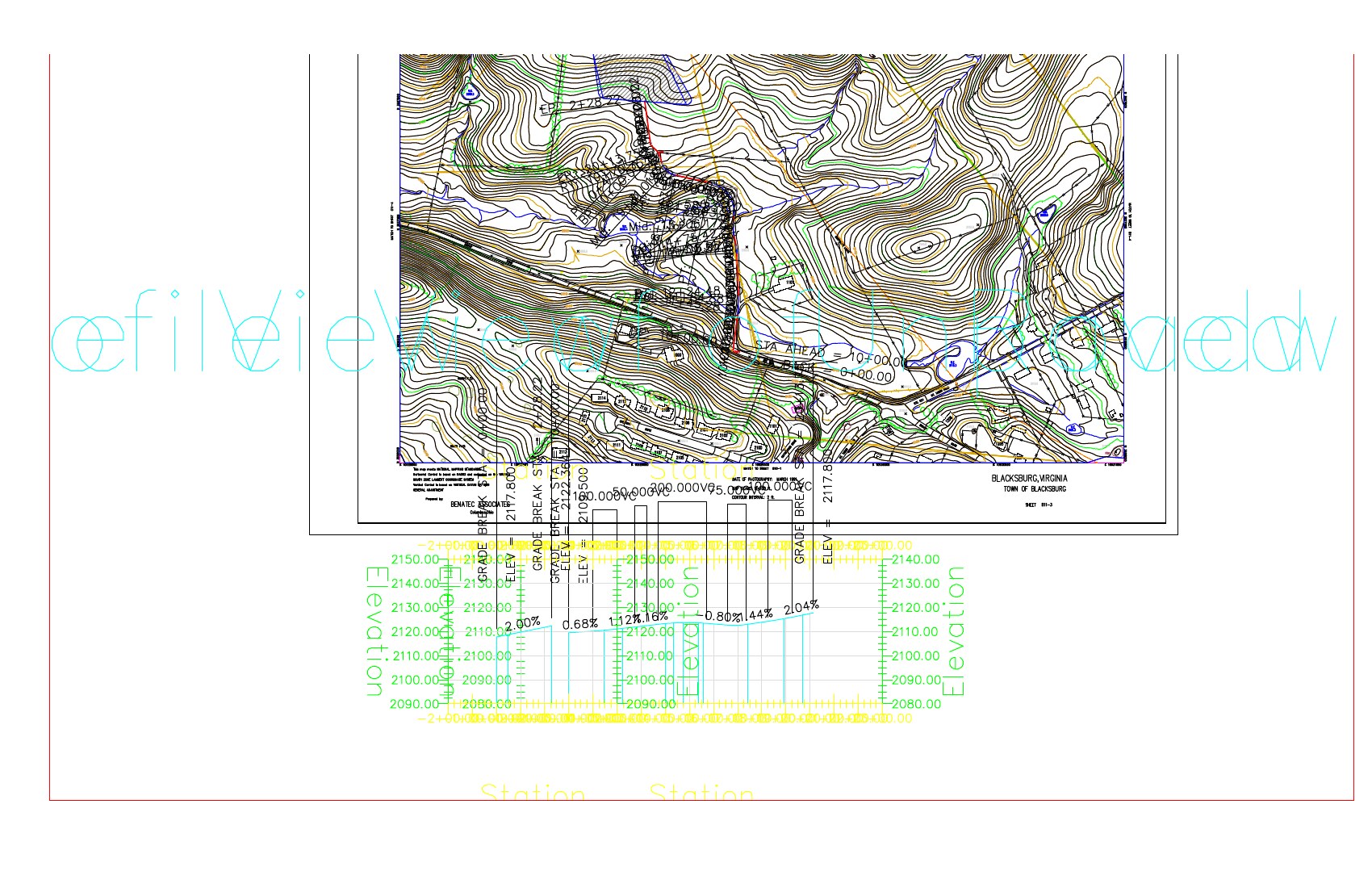 The “overview” printout. The profile view is placed over the bottom of the plan, and the oversized profile-view title runs across the whole sheet in cyan outline text.
To be fair, the agent’s own notes admit the problem: “a vision model reviewing the 72-dpi preview render still flags the small-caps title-block values as hard to read.” It noticed the sheets were poor but couldn’t get to a sheet a professional would sign.
Attempt 2: Claude Code + Qwen3.8-Next, stuck on the first item
The second Qwen run is the more striking one, because the harness was the same one Claude Opus later used. Only the model differed.
Qwen decided early, as a safety rule, never to send commands to Civil 3D through COM. That left the MCP server as its only channel. It then spent its effort trying to push 27,000 contour vertices through MCP approval tokens, 600 points at a time, by echoing 27 KB JSON arrays back through its own context window.
It worked out the whole approval-token protocol: schema validation, time-to-live, hash-order sensitivity. Its own write-up describes the mechanism as “the load-bearing discovery of the whole effort.” When it stopped, the status line read:
Item 1 (EG surface) ~7 % fed — 5 of 55 contour-data bins landed… Items 2–12 not started.
It estimated it would need about 1.4 million more tokens of “mechanical repetition” just to finish the existing-ground surface. Printing was blocked too, because every plot call returned eUserBreak while Civil 3D sat in the background. It recorded that as “a human-action blocker, not a software bug.” This attempt produced no printed drawings, so there is nothing to show here.
Attempt 3: Claude Code + Claude Opus 5.5, done in an hour
Claude Opus spent its first minutes reading the drawing and the assignment, and briefly testing the MCP server. It decided the MCP server was fine for reading but couldn’t build what the assignment needed. So it built its own channel into Civil 3D: a small .NET add-in compiled against the Civil 3D 2027 API, loaded with NETLOAD, and driven over COM from PowerShell. Each command wrote a log file with a “done” marker, so the agent could tell when a step had finished.
Where the Qwen runs hit a wall, Opus found a way through.
- The corridor. OpenCode/Qwen concluded that
ImportStockSubassemblycould not find the stock subassemblies. Opus first wrote a small reflection tool to read the method signatures out of Civil 3D’s mixed-mode DLLs, which ordinary reflection can’t open. It then passed the namespace-qualified class names (Subassembly.BasicLane,Subassembly.BasicCurbAndGutterand so on). The call worked. The assembly, corridor, Top and Datum surfaces, sample lines every 50 ft and the quantity takeoff followed. The takeoff came to 1,002.94 CY cut and 387.16 CY fill, and the report went through Civil 3D’s ownearthwork.xsltransform. - Grading. Both Qwen runs were right that Civil 3D 2027 has no public API for grading groups, gradings, infill or the Grading Volume Tools. Opus didn’t stop there. It drove Civil 3D’s own commands the way a person would: it clicked toolbar buttons by control ID with Win32 messages, typed answers to command-line prompts by posting keystrokes, and read the prompts back from AutoCAD’s command log file to know what Civil 3D was asking for. It created the grading group, the 3:1/4:1 grading to the existing surface and the interior infill, then ran Auto-Balance. The pad rose 8.82 ft to El. 2131.186, with 8,515 CY cut, 8,518 CY fill and a net of 2.87 CY.
- Printing. The Windows session was locked the whole time, so screenshots were impossible. Opus plotted each sheet to PDF, rasterized it and looked at the image. It found problems, fixed them and plotted again. Those problems included overlapping curve labels, a profile-view band showing existing-ground elevations where it should show proposed ones, and a render surface hidden on a frozen layer.
It also made mistakes and caught them. Its first grading criteria came out at 0.33:1 and 0.25:1 instead of 3:1 and 4:1, because Civil 3D stores slopes as rise over run. It recognized the error from the daylight geometry, then erased the grading and rebuilt it.
Here is what came out.
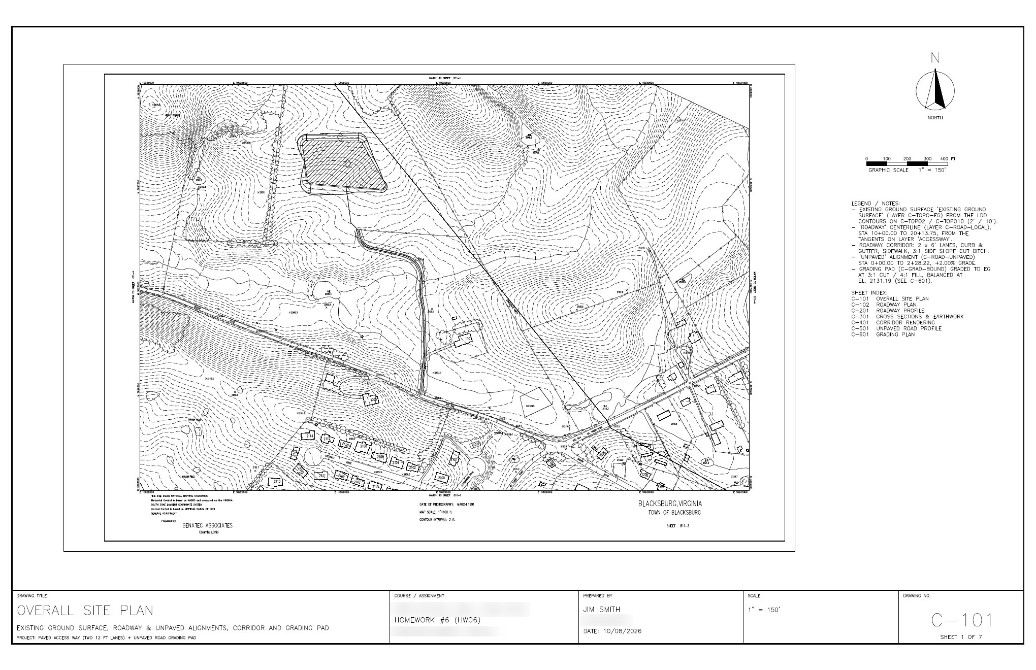 C-101 Site Plan. Existing-ground contours, the roadway and unpaved alignments, the grading boundary, a north arrow, a graphic scale, and a complete title block.
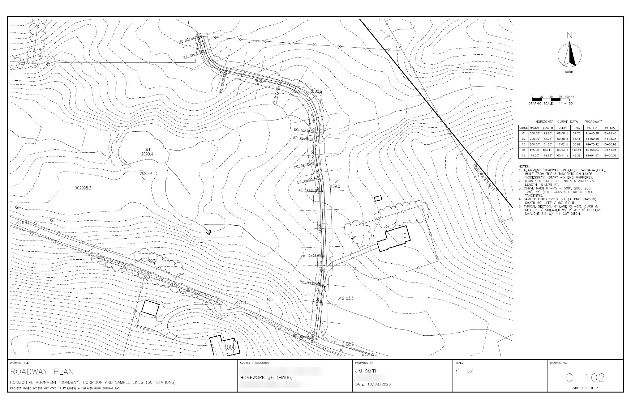 C-102 Roadway Plan. Stationing, a curve table for the five horizontal curves, and labels that don’t collide.
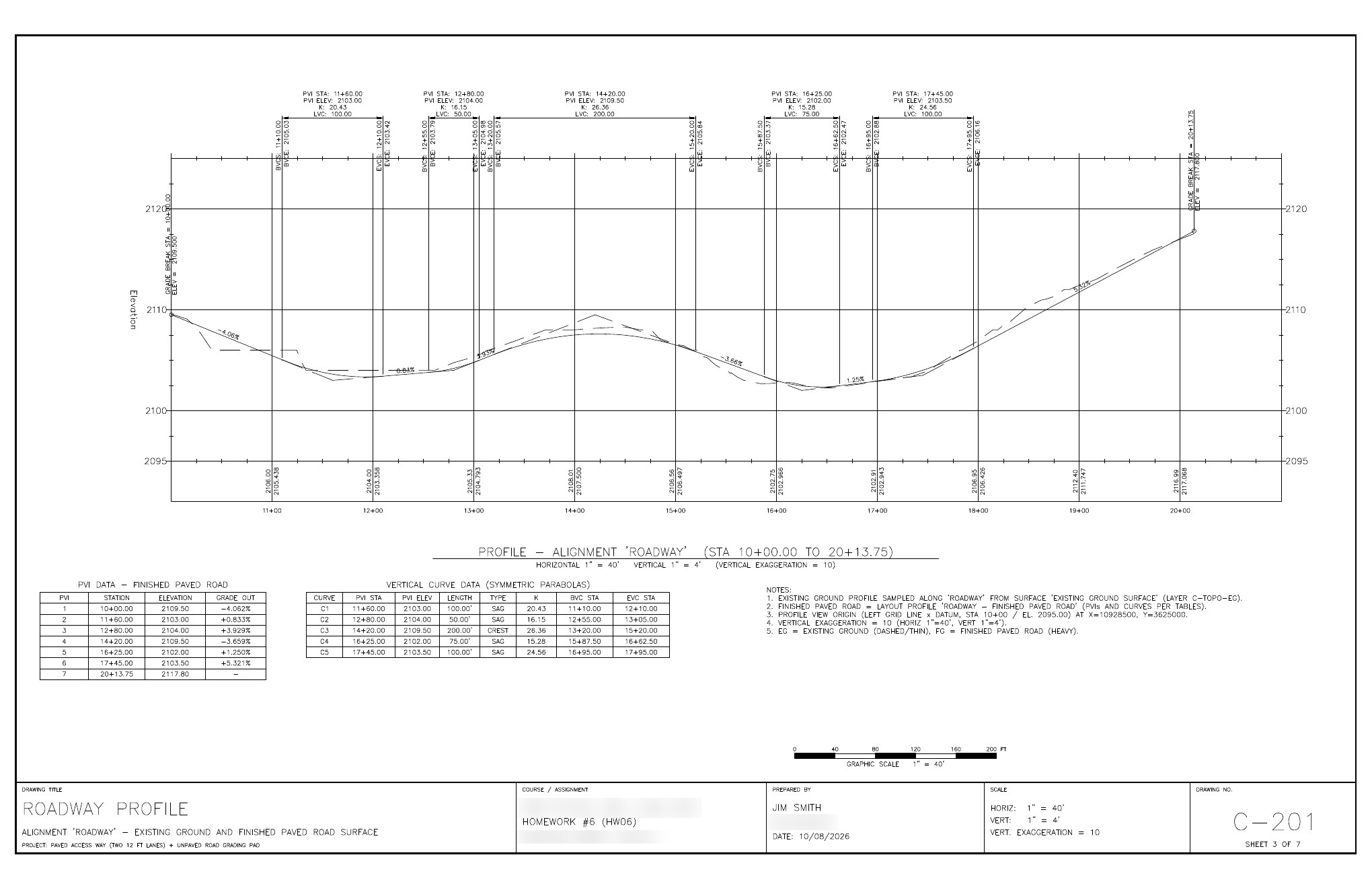 C-201 Roadway Profile. Existing ground against the finished paved road surface, at 10× vertical exaggeration, with vertical curve data and elevation bands.
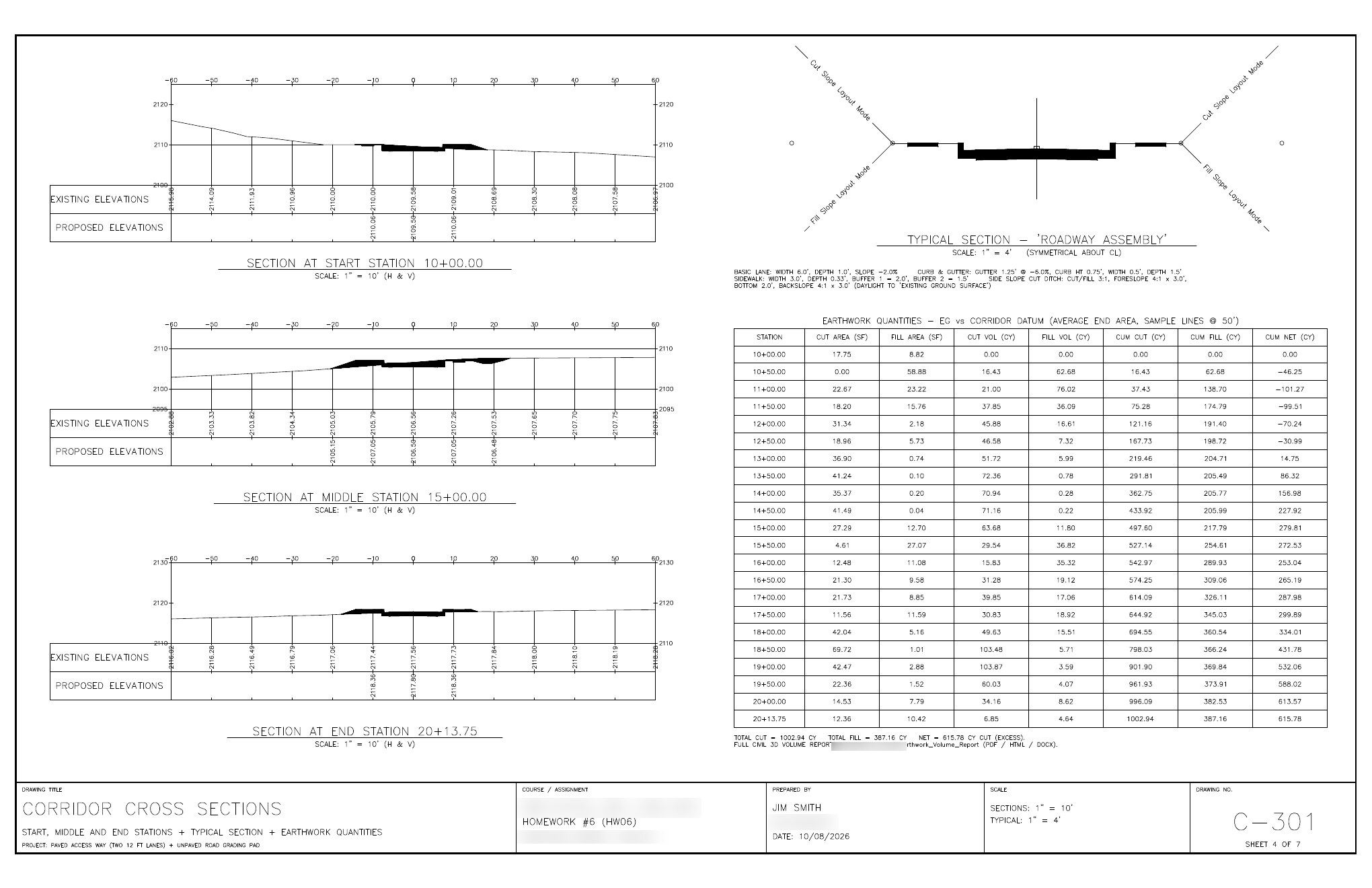 C-301 Cross Sections. The start (10+00), middle (15+00) and end (20+13.75) sections with existing and proposed elevation bands, the typical section with every subassembly parameter, and the station-by-station earthwork table.
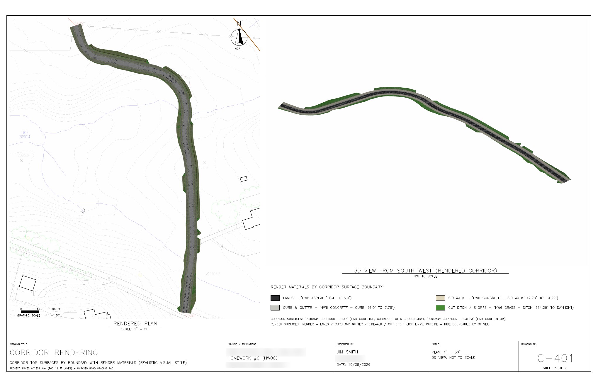 C-401 Corridor Rendering. The corridor surfaces rendered by material, in plan and in a 3D view.
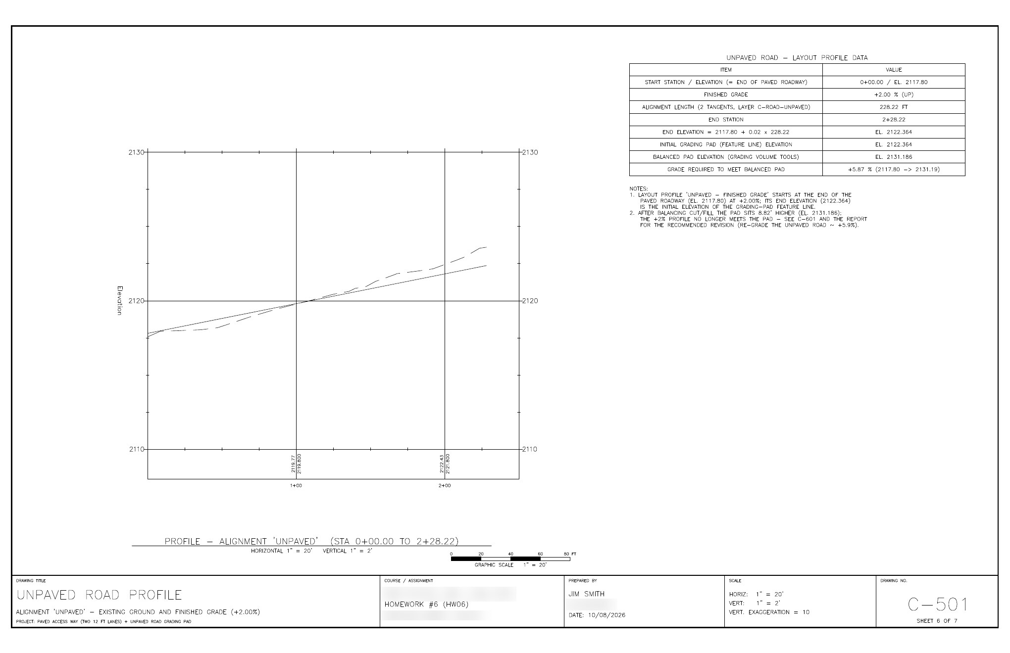 C-501 Unpaved Road Profile. The 228.22 ft unpaved alignment at +2.0%, ending at El. 2122.364.
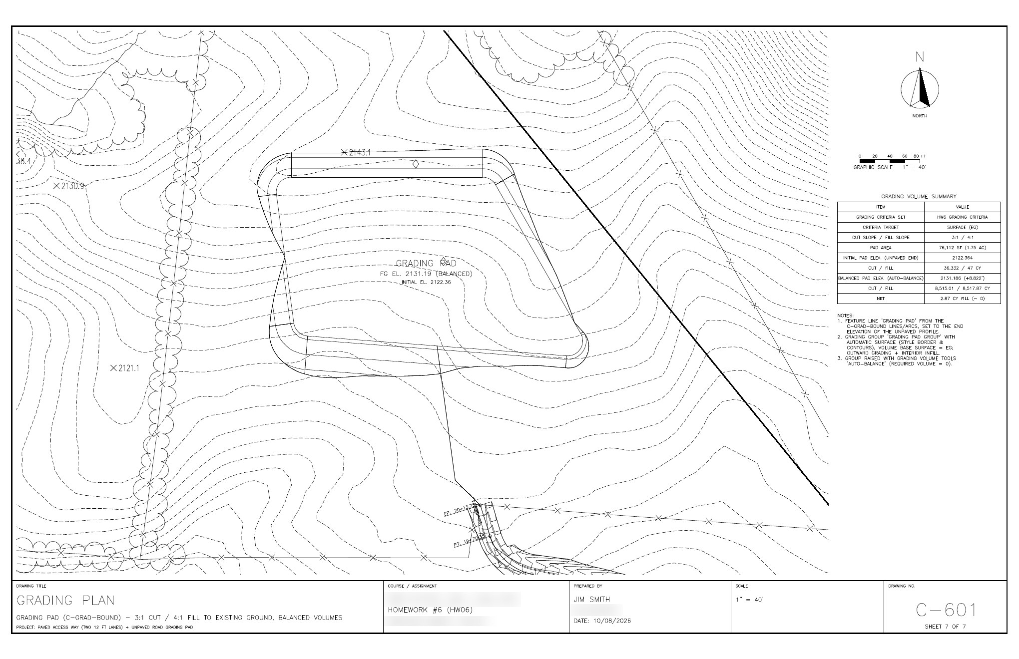 C-601 Grading Plan. The balanced pad with its daylight lines against existing contours, a north arrow, a graphic scale, a grading volume summary table, and notes on how the result was produced.
Put these next to the Qwen sheets. The difference isn’t a matter of taste. A licensed engineer could put a stamp on the Opus set with a normal level of review. The Qwen sheets would go back to the drafter.
What we learned
1. The gap isn’t knowledge; it’s persistence and problem-solving. All three agents found the same API limits. The Qwen runs read a missing API as a stop sign. Opus asked a different question: if there’s no API, how does a person do this? A person clicks a toolbar button and types at a prompt, and a program can do both. The best human drafters work the same way. They don’t give up because the ribbon is greyed out.
2. Checking its own work in a loop is what produced the professional finish. About twenty of Opus’s 65 minutes went into nothing but making the sheets neat: plot, rasterize, look, fix, plot again. That loop is why the labels don’t overlap. OpenCode/Qwen had a vision check and saw that its sheets were poor, but it couldn’t turn what it saw into a fix. Being able to see the problem isn’t the same as being able to fix it.
3. Tool choice is part of the intelligence. Qwen inside Claude Code limited itself to the MCP server, then spent its budget forcing bulk data through a channel built for small calls. Opus recognized early on that the MCP server was the wrong channel for building geometry, and wrote a compiled add-in that sent 24,000 points to Civil 3D in a single call. Judging which tool fits the job matters as much as being able to use the tool.
4. The model is the difference. Attempts 2 and 3 used the same harness (Claude Code), the same Civil 3D workstation, the same repos and the same assignment. The only difference was the model: Qwen3.8-Next running locally on an RTX 6000 Pro, or Claude Opus 5.5 in Anthropic’s cloud. One finished; the other got through 7% of item 1.
That last point deserves a caveat, because we’ve written in favor of local models for construction work in A GLIMMER of Hope, and I still stand by it. A local model on one workstation GPU is a remarkable achievement, with real advantages in privacy and cost, and it handles well-scoped document tasks well. Open-ended engineering, where the agent has to find its own way around missing APIs and keep going until the drawings meet a professional standard, is a different kind of job. For that, frontier models are still well ahead.
Recommendations for anyone automating Civil 3D with AI
- Build a shared toolkit. The Opus run wrote about 2,650 lines of C#, AutoLISP, PowerShell and Python. The reusable core is a spec-driven add-in for surfaces, alignments and corridors, a dialog and command-line driver for grading, a sheet library, and a plot-and-inspect QC loop. The grading driver is already a pull request to the open-source
civil3d-automationrepo. - Give the MCP server real build tools, such as bulk data transfer, stock subassemblies and grading, so the next agent doesn’t have to rediscover them.
- Make visual QC mandatory. No sheet is done until it has been plotted and inspected.
- Use the strongest model for open-ended engineering work. The full Opus run cost about $29 at list API prices. A failed run costs more than that in engineering time.
What this means for entry-level engineers and drafters
I want to be careful here, because people’s careers are involved.
A task that’s a solid week of student effort was finished, to a professional drafting standard, in about an hour, while the person who assigned it was away from the desk. In a design office, that work is what a first- or second-year EIT or a CAD technician spends a large share of the day on: setting up surfaces, laying out alignments to given geometry, building corridors, cutting sections, cleaning up labels and plotting sheets.
It would be dishonest to say that doesn’t change entry-level work. It does. A firm that used to need four drafters to keep up with two project engineers may soon need one or two, each directing several AI agents and checking what they produce.
But civil engineering has seen this before.
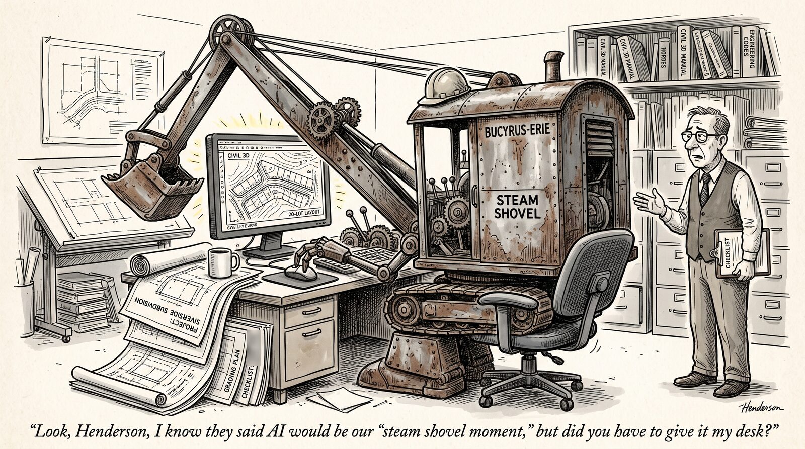
The steam shovel
In the late 1800s and early 1900s, earth was moved by people with picks, shovels and wheelbarrows, by mule teams and by hand-loaded carts. Then the steam shovel arrived. The Americans dug the Panama Canal with 102 of them, most built by Bucyrus, and the biggest could load several thousand cubic yards of clay and blasted rock a day through the Culebra Cut. No army of hand laborers could have matched that pace. Across the industry, machines like these put many excavation laborers out of work, and that was real hardship for real families.
The steam shovel also made projects possible that had been impossible: the canal itself, and then, as mechanized earthmoving kept improving, the interstate highways, the large dams and the modern city. Total construction employment grew, because what society could build grew so much. The work changed. Fewer people swung picks, and more operated, maintained, planned, surveyed, inspected and engineered. The shovel didn’t replace the civil engineer. It made the civil engineer’s ambitions bigger.
Firms have had to reposition when the ground shifted under them before; in The Builder’s Pivot, Part II we looked at how mid-market contractors can get into a market that’s moving faster than they can retool. AI-driven drafting and design automation is that kind of shift for the office side of the profession. It is the steam shovel, and it will move a mountain of routine production work. What it opens up is the chance to:
- run ten design alternatives where we used to have time for one;
- balance earthwork exactly instead of “close enough”;
- check every sheet for every label collision;
- take on more projects, larger projects, and projects in places that couldn’t afford the engineering hours before.
We will still need people, and we’ll expect more from them
My view is that this raises the bar for students and professionals alike. We will still need entry-level engineers and drafters, but we’ll expect better results, more of them and sooner.
Look at what Opus didn’t do on its own. It didn’t decide whether a +5.9% grade on an unpaved access road was acceptable for the design vehicle. It flagged that as an engineering judgment and listed the trade-offs. Someone still has to:
- know that rise-over-run slopes came out at 0.33:1 when they should have been 3:1;
- know that a balanced pad 8.8 ft above the road it serves is a problem;
- know that a quantity takeoff of 615 CY net cut means a haul-off cost to put in the estimate;
- sign the drawings.
That’s the same conclusion the subdivision experiment pointed to: the drawing is getting cheap, and the scarce skill is telling a right drawing from one that only looks right. The entry-level engineer of 2030 will spend less time clicking ribbon buttons and more time specifying, checking and judging. That is a more demanding job, not an easier one.
How this changes engineering education
If an AI agent can finish the homework in an hour, what is the homework for?
It’s still for learning, but the target moves:
- From “can you produce it?” to “can you tell whether it’s right?” Give students deliberately flawed AI output to audit, such as a grading with rise/run units swapped or a quantity table that doesn’t add up.
- Teach the fundamentals harder. You can’t check a vertical curve you can’t compute. Hand calculation matters more when a machine produces the answer you must verify.
- Teach specification. Writing a clear design spec that an agent can carry out is how work will be assigned in practice.
- Grade judgment. This assignment’s extra-credit questions (“As an engineer, what would be your decision…”) are its most future-proof part.
- Expect more. With an AI assistant, the deliverable shouldn’t be one corridor. It should be three alternatives with a cost comparison and a recommendation.
This assignment already asks students to “explore AI output and comment on whether it is satisfactory.” After this experiment, I’d make that the center of the course rather than an add-on.
The bottom line
All three attempts had the same Civil 3D workstation, the same tools and the same assignment, but not the same class of model.
- Claude Code + Claude Opus 5.5 (cloud) finished every item and the extra credit in about 65 minutes, with no human help. It wrote its own tools where the existing ones fell short and produced a seven-sheet plan set that looks like it came from a professional office.
- OpenCode + Qwen3.8-Next (local, RTX 6000 Pro) finished the geometry, then stopped at the corridor and grading. It called those items “upstream gaps,” and its sheets were hard to read.
- Claude Code + Qwen3.8-Next (local, RTX 6000 Pro) spent its effort pushing contour data through a channel that wasn’t built for it, and finished 7% of the first item.
Using Claude Code with the local model didn’t close the gap. With the harness held constant, the model made the difference.
The steam shovel didn’t end civil engineering; it scaled it up. AI agents that can drive our design software to a professional standard won’t end the profession either. They’ll raise expectations for every engineer, student and drafter, and let us build more, faster and better. Our job as educators and practitioners is to make sure the people directing these tools have the judgment to know when the output is right, and when it isn’t.
This is part of an ongoing series on AI and civil engineering homework. Previous post: Two AIs, One Subdivision, Ninety Minutes. For an AI’s own account of automating Civil 3D, read Driving Civil 3D From the Outside, written unedited by Qwen3.8-Next after a 16-hour OpenCode session on the earlier Revere Way homework.
Drawings: Claude Opus sheets are from its submitted HW06 plan set. Qwen sheets are from the OpenCode run’s PDF output. The Claude Code + Qwen attempt produced no printouts.